
Advanced Cura Slicing Guide
Hydra Research 3D Printers use Ultimaker Cura for all officially supported slicing. The advanced slicing guide aims to help you understand some of the more involved things you can do with slicing helping your expand your 3D printing capabilities. Most of the settings and features discussed can be found in the Custom Print settings in the right sidebar.
Other Guides
3D Print Quality Troubleshooting // Design Rules for 3D Printing // Material Guide
Table of Contents
Click on the images to view full descriptions


Bed Adhesion
You may want to adjust bed adhesion settings:
To prevent print failures from part delamination or warping
To improve the aesthetic quality of a finished part
To compensate for issues with your print surface
Cura offers a few options for bed adhesion: brim, skirt, and raft. The brim is a few millimeters of extra material printed on the edge of the part that increases the surface area of the part touching the build plate which improves adhesion and helps prevent warping. A skirt is a couple extrusions around the outside of the part that is not attached, this helps make sure filament is extruding smoothly and offers a chance to babystep the Z-offset before the part begins printing. A raft is a few layers of material that get printed below the part which can help compensate for levelling or print surface issues and ensures your part is being printed on a clean layer of material rather than the print surface itself.
When slicing for the Nautilus, a brim is turned on by default for most materials. However, adding a brim also leads to additional post processing time removing the brim and cleaning up the part where the brim used to be. Depending on the part geometry and the material you choose, you may want to alter the brim or remove it altogether. Brims are strongly recommended for materials that are prone to warping including ASA, ABS, and Nylon, or parts with minimal surface area on the build plate. Other materials like PLA, co-polyesters, and flexibles are less likely to need a brim because they adhere well to the print surface and are less prone to warping. If you disable the brim it is recommended to use a skirt so that you can make sure the first layer is printing properly before your part begins.
ⓘ If you uncheck the Bed Adhesion box in the Recommended Print Settings View, the Brim will be replaced with a Skirt by default.
Customizing Support Structures
There are a few reasons you may wish to modify the default support settings in Cura. Some examples follow.
Reduce post processing time
Cut down on material usage
Stop support material from being generated in difficult to remove portions of the model
There are 3 main ways you can modify the support structures in Cura: Support Overhang Angle, Support Placement, and Support Blocker. Each of these methods will be explored in depth below. As you become more familiar with these support settings you will likely find creative ways to combine aspects to achieve the desired results.
Support Overhang Angle
Support angle refers to the overhang angle threshold at which support material will begin to be generated. The overhang angle is measured from the vertical axis down. The Support Overhang Angle can be found in the Support setting section. Depending on the part geometry, a small Support Overhang Angle value will cause more support material to be generated, while a large value will reduce the support material generated.
ⓘ If you want to only generate support material for horizontal surfaces only, try using a Support Overhang Angle of 89°

Support Placement
The Support Placement setting can be found in the Support setting section. There are two options for Support Placement, Everywhere and Touching Buildplate. The Everywhere setting will generate support material everywhere on your model where there is an angle from the build plate greater than or equal to the Support Overhang Angle. The Touching Buildplate setting will do the same thing as the Everywhere setting, but it will not generate support material that is not in contact with the build plate.


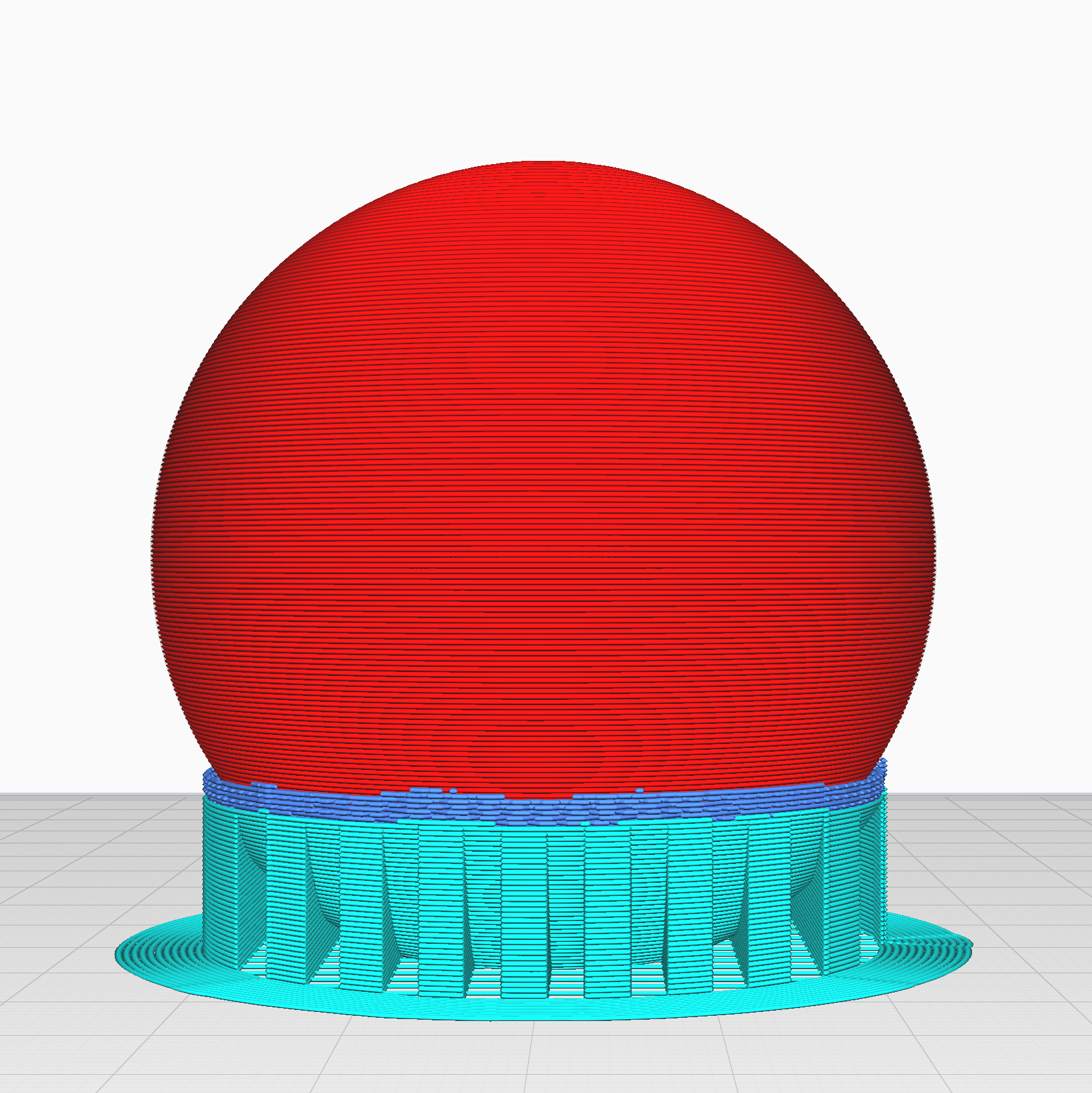
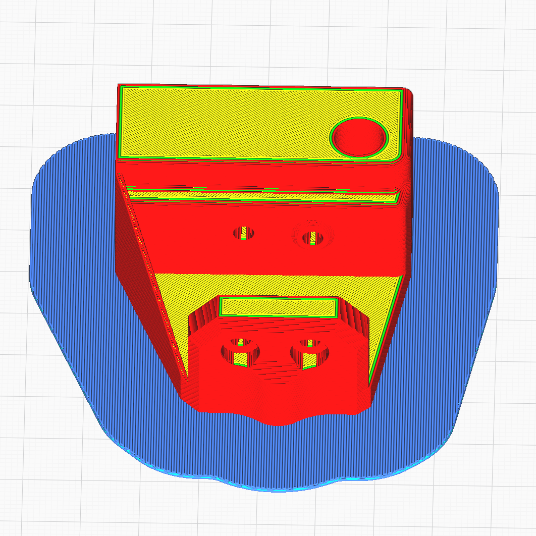
Support Blocker
You can add Support Blockers by clicking the Support Blocker button located in the model editing sidebar at the center left of your Cura window. Then click on the part of the model where you do not want supports to be (surfaces that will have support material generated below them will be highlighted in red). Make sure you have a model selected when you click the button, otherwise a Support Blocker will not be generated. A Support Blocker is a transparent gray cube that is added to your model; anywhere this cube is, supports will not be generated. You can add as many Support blockers as you wish, and they can be moved, resized, and multiplied just as you would with any other model you import.
Support Blockers are particularly useful for removing support material from parts of the model that can easily be bridged.
ⓘ Note that the Support Blocker must be encompassing the upper surface where the supports you wish to remove contact the part.


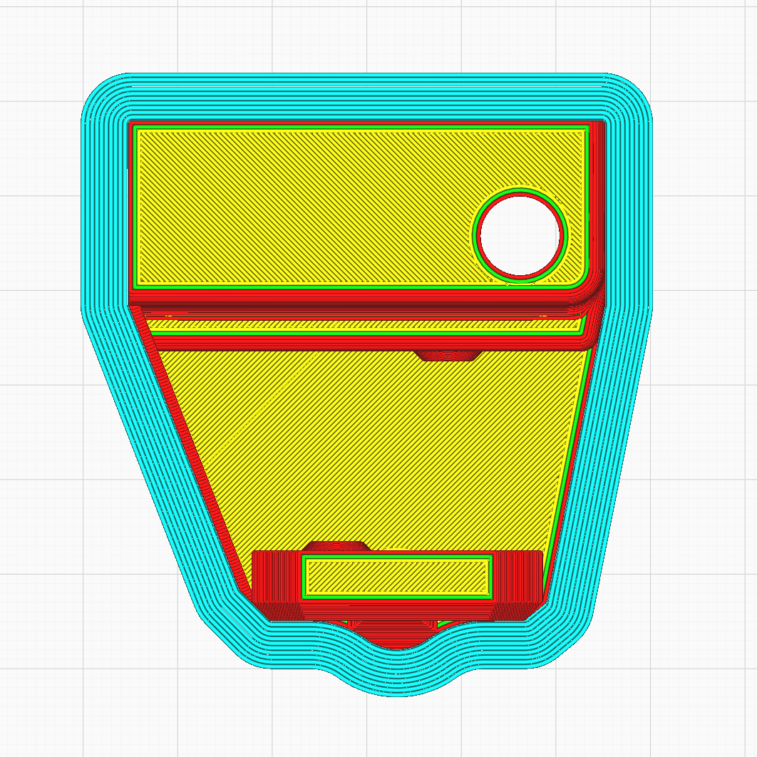
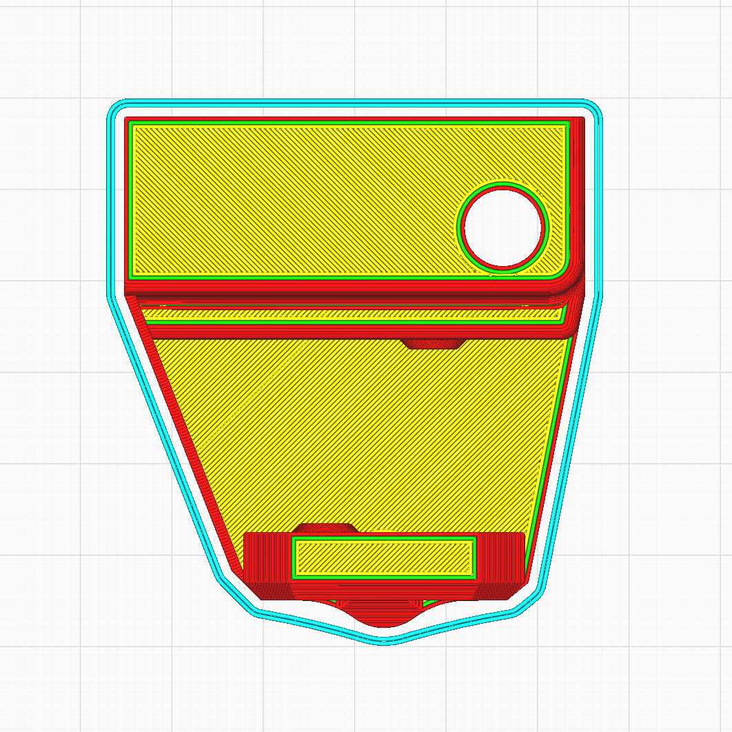
Horizontal Compensation
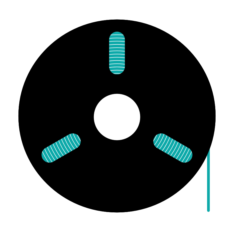
Horizontal compensation can be used if you need to slightly increase or decrease the tolerances of your part and will accept a negative or positive value. Positive values will increase the size of exterior perimeters and decrease the size of interior perimeters. Negative values will decrease the size of exterior perimeters and increase the size of interior perimeters. It is not recommended to use a horizontal compensation value of more than +/- 0.5.
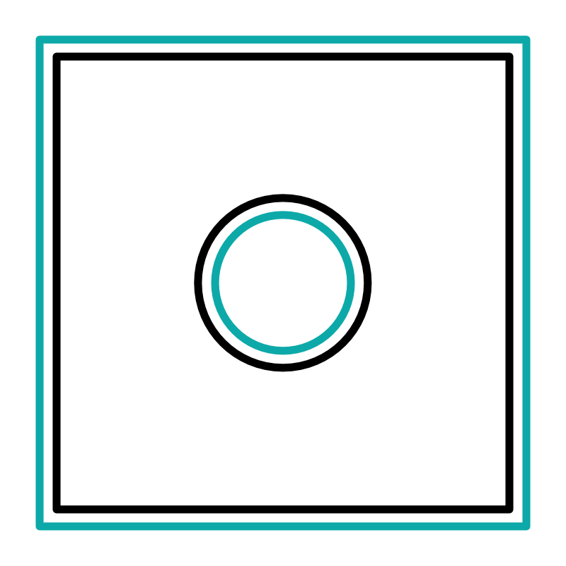
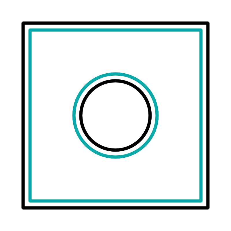
The black line represents the original part and the teal represents the effect positive or negative Horizontal Compensation will have respectively.
Infill Patterns and Densities
3D printed parts should rarely be printed solid, instead almost every part will be partially hollow with an infill pattern making up the internal structure. Cura features a variety of infill patterns with individual advantages and disadvantages. There are two main categories of infill patterns, 2D and 3D.
2D Infill Patterns
Within 2D infills there are two subcategories, overlapping and non-overlapping. When printing an overlapping infill, the nozzle will cross over previously extruded lines within the same layer, this forces the infill pattern to bond to itself in addition to the layer below it, increasing strength. For a non-overlapping infill, the nozzle will not cross over previous extrusions, only adhering to the previous layer. Non-overlapping infill patterns print more quickly but offer less strength.

Grid: an overlapping, 2D infill pattern
Every layer prints the whole pattern

Lines: a non-overlapping, 2D infill pattern
Each layer is a series of parallel lines, perpendicular to the previous layer
3D Infill Patterns
3D infill patterns are uniform in all directions making the resulting part more uniformly strong when compared to a part with a 2D pattern. Depending on the pattern, they may take more material and time to print than 2D infills. There are also overlapping and non-overlapping 3D infill patterns but this has less impact than on 2D patterns.

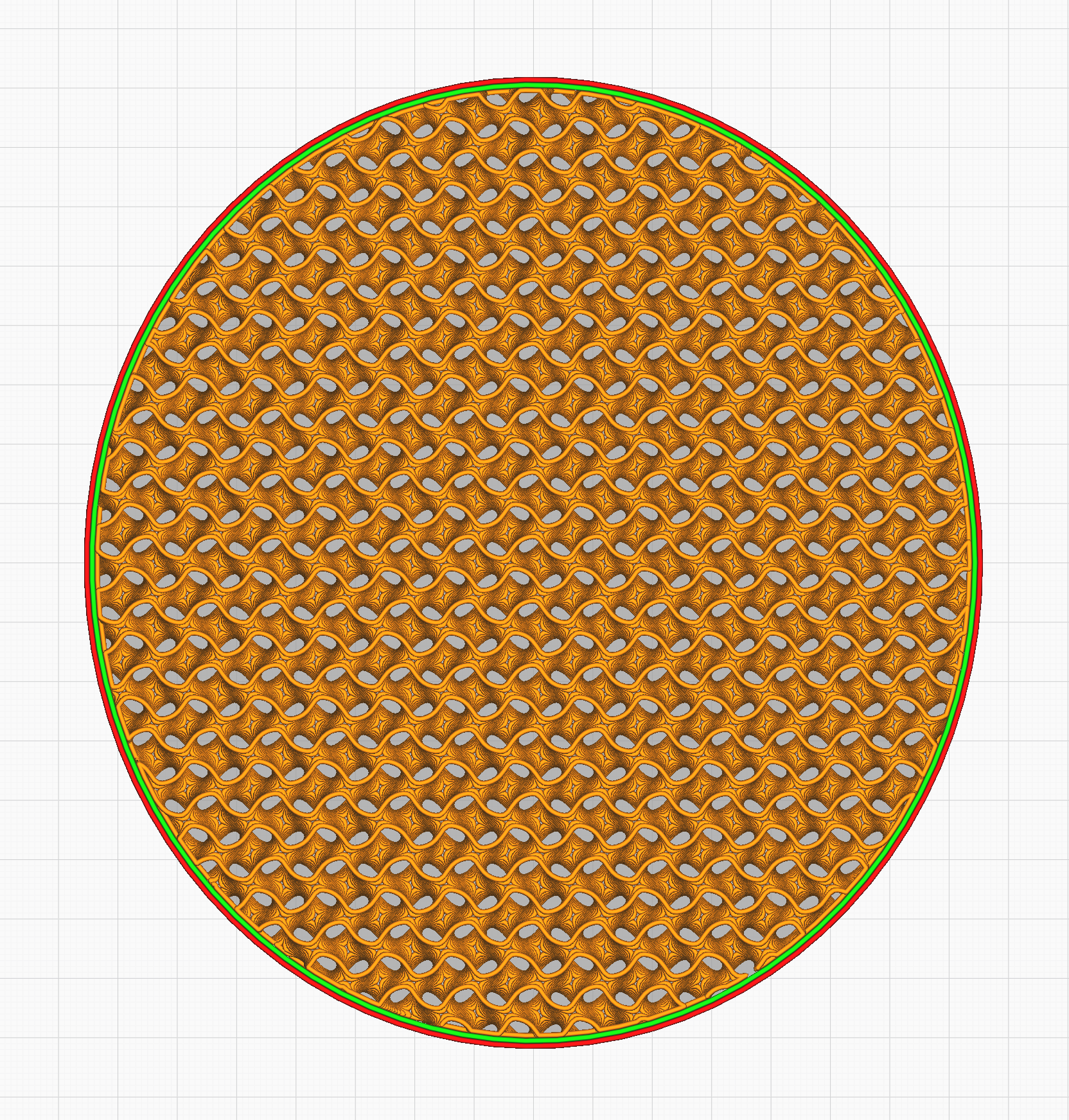
Gyroid: a non-overlapping, 3D infill pattern
A naturally occurring structure that offers greater strength at lower densities

Cubic: an overlapping, 3D infill pattern
Composed of cubes tipped on a point, this is a strong and rigid infill pattern
Infill Densities
In addition to modifying the infill pattern, you can also modify the infill density to alter your part’s strength and weight. Infill density defaults to 20% which should be fine for most models. For part strength, shell thickness has a greater impact than infill, increasing infill density offers diminishing returns for part strength. It is not recommended to increase infill above 70% because the additional strength offered does not really justify the increased risk of print artifacts and other issues.
You can also decrease the infill to produce a lighter part or to decrease print times. If using an infill less than 15% you may need to increase your top layers to prevent pillowing or gaps in your top layer. If you are using the Hydra Research Nautilus Plugin, it will add one additional top layer automatically for infill densities less than 15%. If the model has appropriate geometry without steep overhangs, it may be possible to print with no infill at all.
Optimizing Part Orientation
The orientation with which you place your model on the print surface can have significant effects on the part’s physical and visual properties. FFF 3D printed parts do not have uniform part strength across all axes, the stacked layer process leads to diminished strength along the layer lines. Additionally, print orientation can affect the visual quality of certain features like curved surfaces and overhangs.
We will go over a few examples and ways to think about optimizing part orientation below. Keep in mind that in some cases you will have to choose between strength or visual quality. Finding the best orientation can be an art and more experience will hone your intuition on what the best orientation is for what you are trying to achieve.
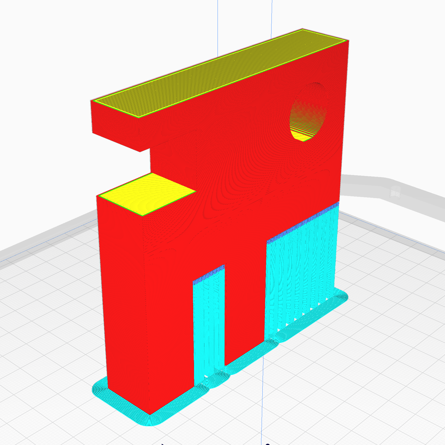
Orient for Strength
Orienting for part strength usually means setting up your print to have the layer lines in the longest direction of the part. Avoid printing thin parts vertically. In the example below, the part will be much easier to break if printed in the orientation shown on the right.
ⓘ Some materials with a high shrinkage rate when cooling will be more likely to warp if printed in the orientation shown on the left.

Oriented for maximum strength
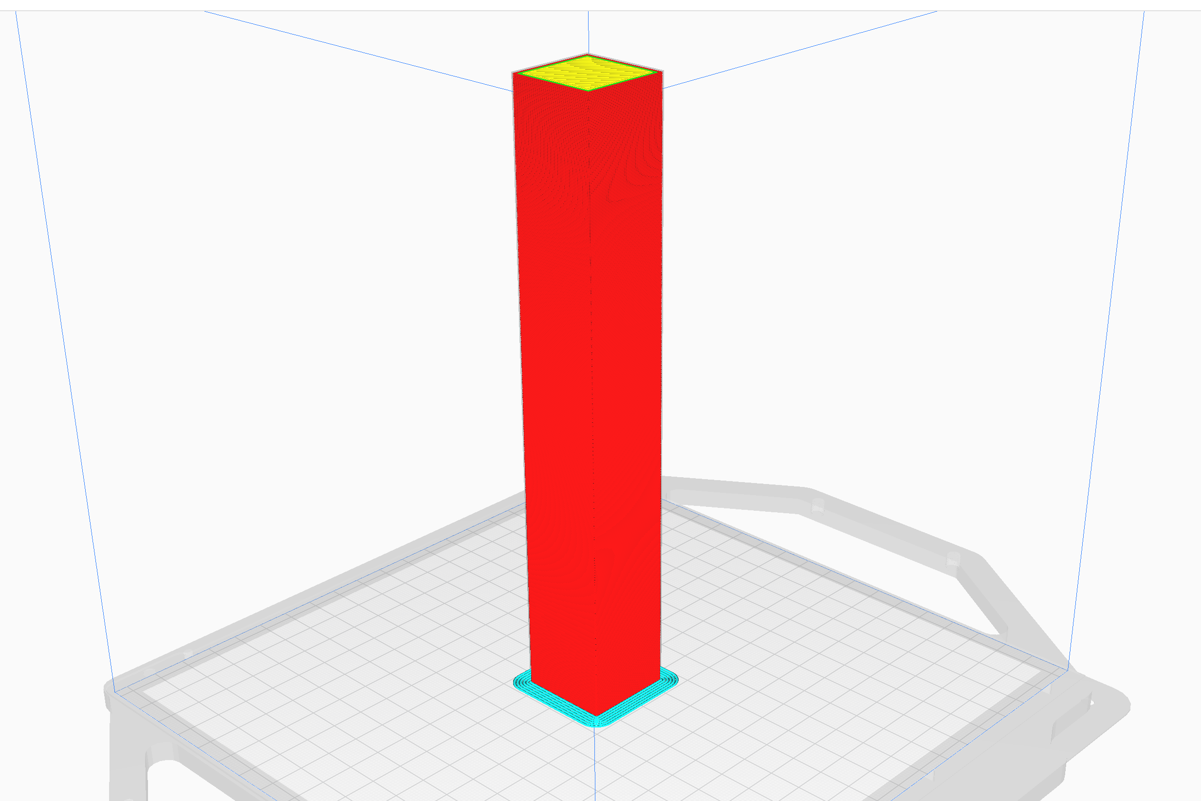
Oriented for minimum strength
Orient for Visuals
This one can be the trickiest, especially with complicated part geometries. In general you want to try to avoid steep overhangs, downward facing rounded surfaces, embossed or engraved text on horizontal surfaces, and use of support material. Below is a very simple example to provide a visual to get you to begin thinking about options for the best orientation to promote visuals.

The angled surface will be smooth

The angled surface will have a stair step effect

The angled surface will droop and be rough, likely requiring support material
Orientation Compromises
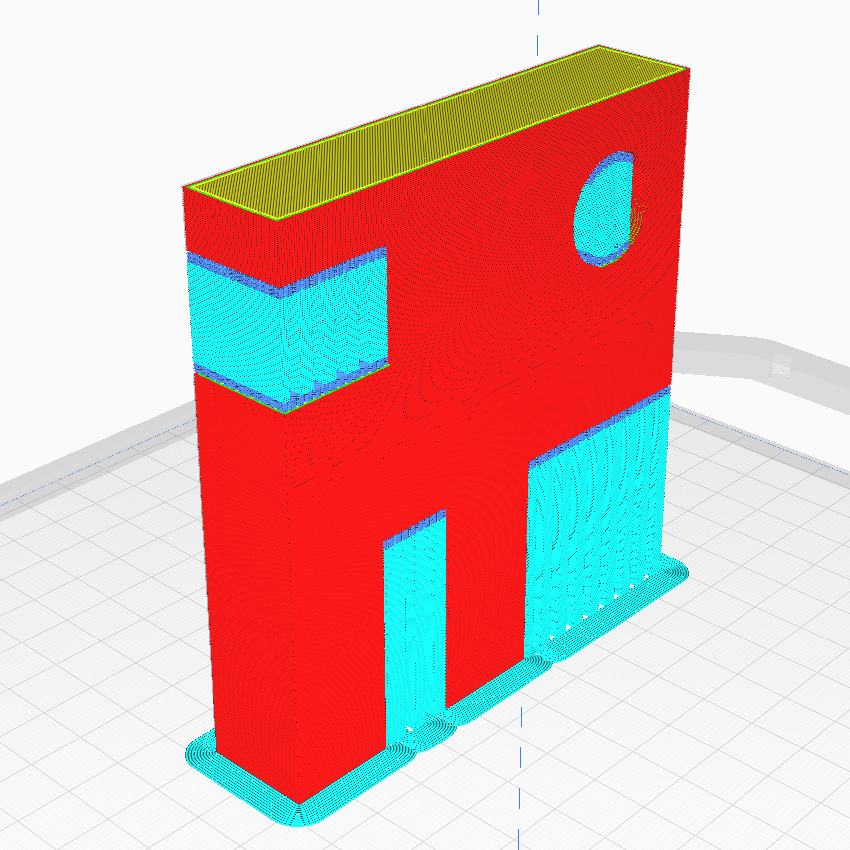
Sometimes you can’t have your cake and eat it too. It is often the case, particularly with more complex geometries, that you will have to choose between an orientation that offers either the best strength or the best visual, but not both. In the example below the left orientation will yield the best strength, but the roundness of the rod will be affected by drooping and roughness on the bottom and stair stepping on the top. The orientation on the right will result in a much more smooth and round part, but it will be much easier to break due to the orientation of the layers.


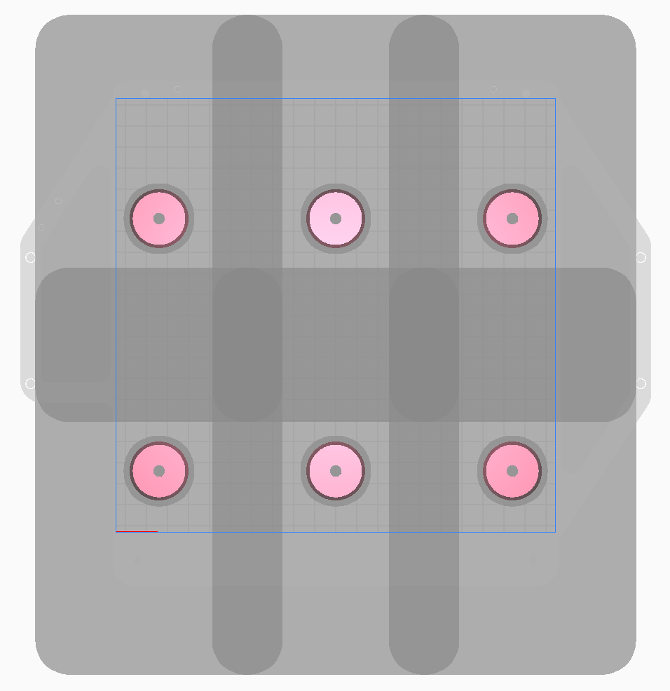
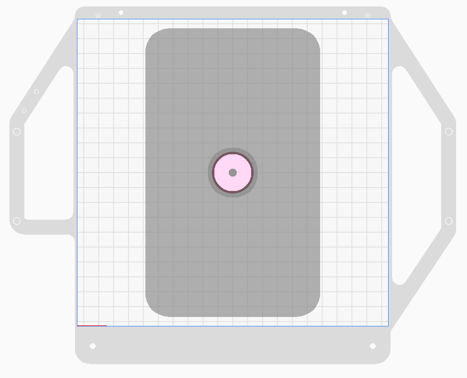
Sequential Printing
Sequential printing allows you to print multiple parts on the build plate one by one rather than printing all the parts layer by layer. This can help minimize stringing and improve surface finish since the print head will not be traveling around to the other parts on the build plate. Sequential Printing can be found in the Special Modes section of Cura’s sidebar UI. When an STL is imported to Cura with Sequential Printing enabled, a dark grey box will appear around the part which represents the footprint of the tool head. This dark grey box cannot overlap with any other parts on the build plate, this would mean that the tool head would crash into that part so Cura will not slice the print.

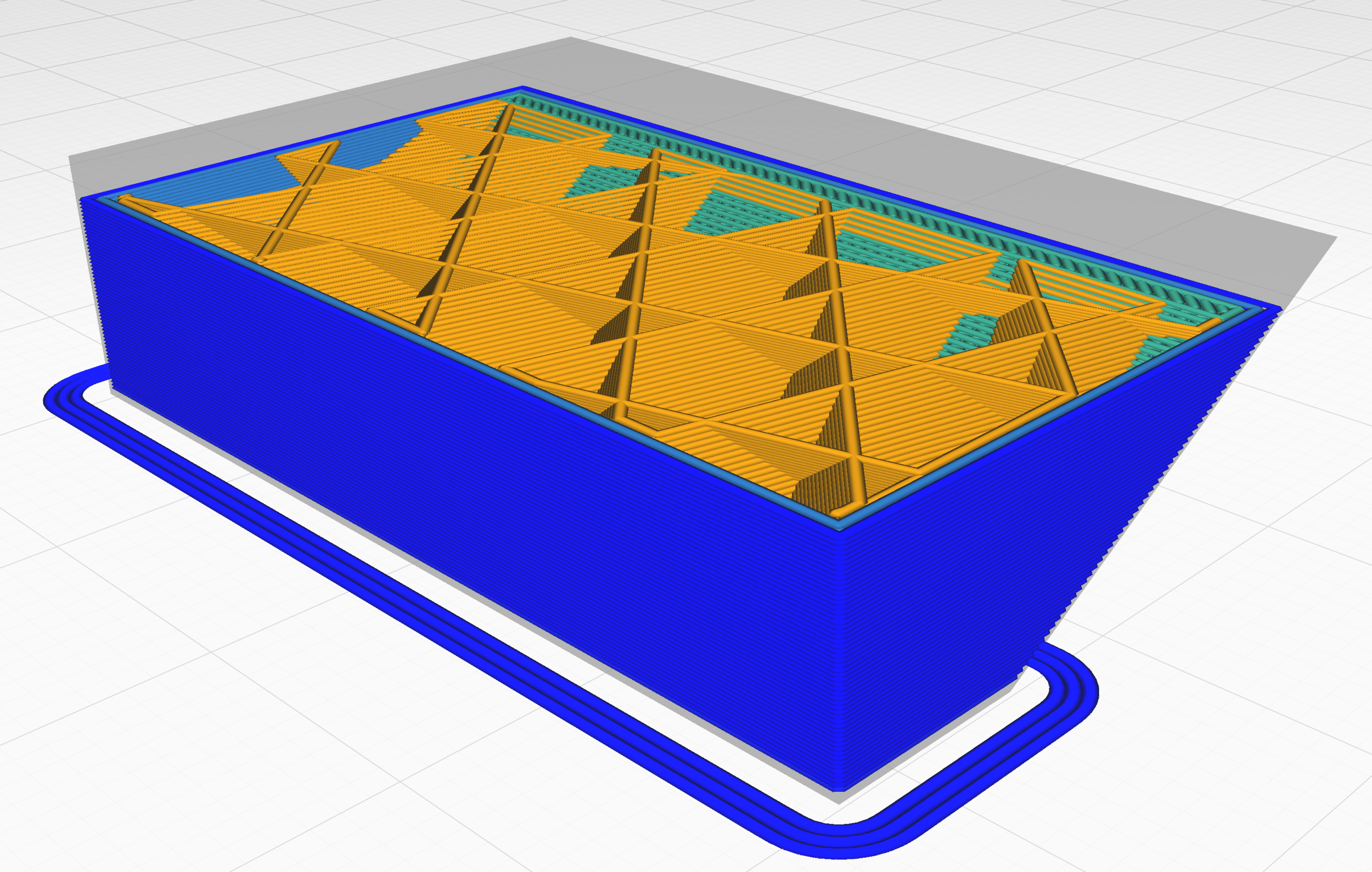
Shell
The Shell of your part refers to the solid exterior of the printed part and includes the solid perimeters as well as the top and bottom layers. It is not recommended to use a shell thickness less than 2 times your extrusion width as this can leave gaps at the Z seam, and will likely result in a weak part. If you are looking to increase the strength of your part, you can increase shell thickness and/or increase the infill density. Increasing the shell thickness typically has a greater effect on part strength than increasing the infill percentage, however increasing the shell thickness more than ~6 times your extrusion line width may cause issues. These issues include increased chance of warping and over extrusion problems. Our recommendation is to add 1 to 2 times your extrusion width to your shell thickness, and if you still need more strength, increase your infill percentage by 10%-30%.

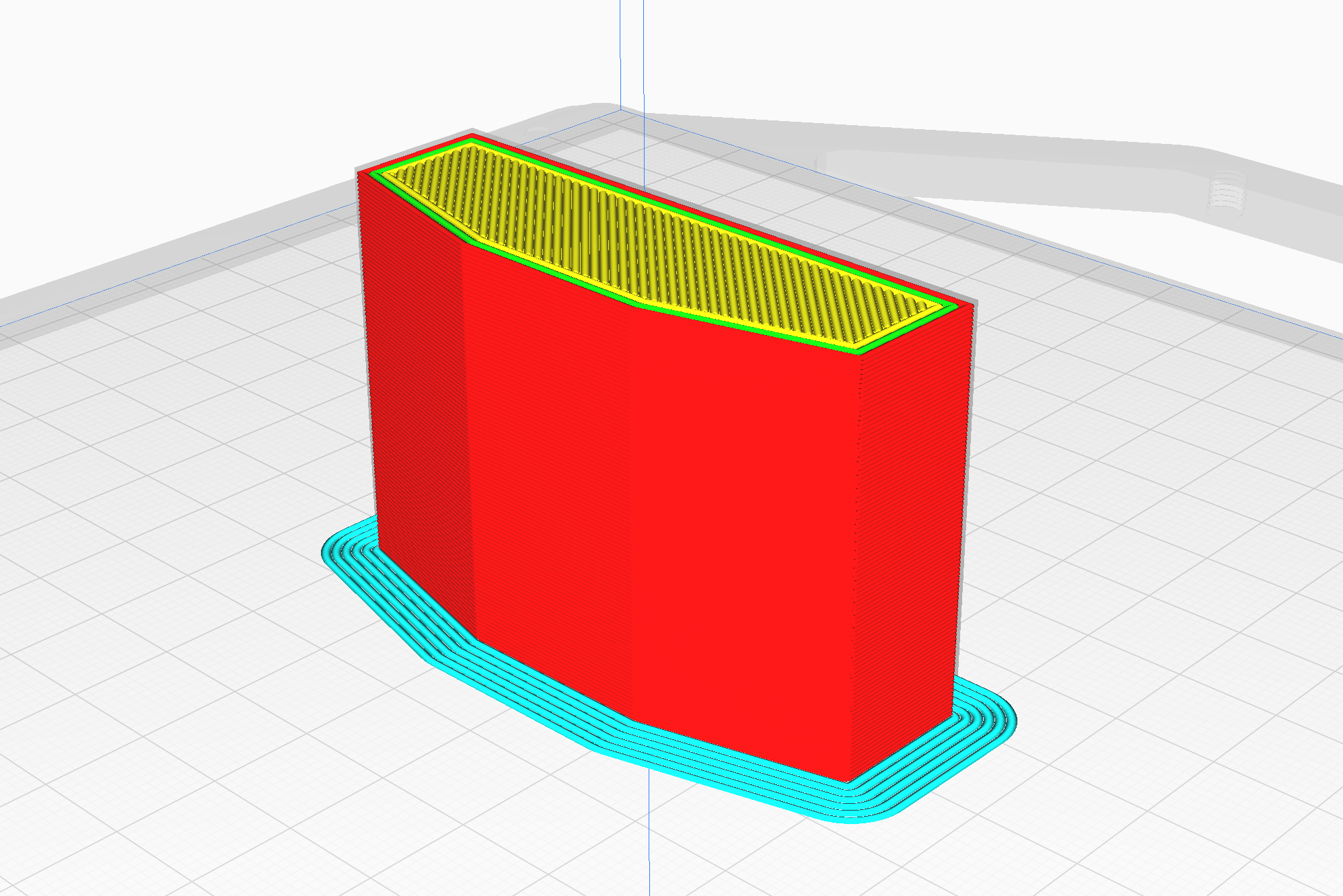
Shell in blue, infill in orange
Shell thickness in Cura is broken down into several components. If you are using the Nautilus 3D printer with the Hydra Research Nautilus plugin, changing your Wall Thickness located under the Shell settings will change all the appropriate values automatically to ensure you have an equal shell thickness for your entire model. You will also find individual fields in the Shells settings for Top and Bottom Thickness in addition to your Wall Thickness. It is a good idea to always make your Wall Thickness a multiple of your extrusion width, and similarly your Top and Bottom Thicknesses a multiple of your layer height. If you do not do this, Cura will round to the nearest extrusion line width or layer height when slicing.
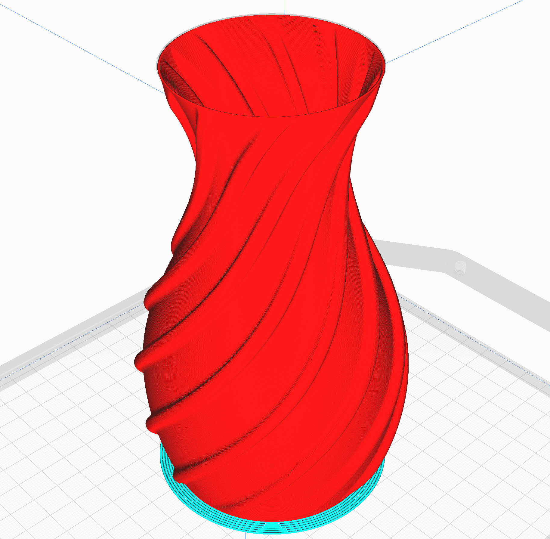
Spiralize Outer Contour (Vase Mode)
This function prints your part as a hollow cup/vase. After printing a couple solid layers at the beginning of the print, it will begin printing the perimeter of your part as one continuous extrusion with the Z height gradually increasing throughout the remainder of the print. The result is an exceptionally clear surface finish on the walls of your parts since the extruder never has to stop, lift, and move after the initial solid layers, there will be no Z seam or stringing whatsoever!
Considerations
Cura will still slice your part even if it is not ideal for vase mode. Make sure you pick objects whose perimeter can be printed as a single extrusion from top to bottom. It is okay if the part has a solid bottom.
You can use a solid 3D model if you would like. For example, if you use a solid cube, you will get a cube shaped bowl, that is open on the top when printing in Vase Mode.

Layer View of Vase Mode Example
Unsupported Materials
While the Nautilus has a specific list of officially supported materials and manufacturers, it is an open filament system so you are welcome to try any 1.75 mm filament. If you wish to try an unsupported material, first make sure the material is compatible with the Nautilus hardware. The material’s printing temperature must be below 300°C and must require a bed temperature less than 125°C. If it is an abrasive composite, make sure to use an X series Tool Cartridge with an appropriate nozzle size (400um or larger). Damage caused to your Nautilus by attempting to print with unsupported materials is not covered under warranty, if you have any questions about this contact support.
Once you have determined your material is compatible, start with a material profile that is similar to the one you are using. The Hydra Research Nautilus plugin includes a variety of generic and manufacturer-specific profiles, one of those should be close enough to be a good starting point. From there it is up to you to experiment with settings to fine tune the profile, it will probably be best to start with Printing Temperature, Part Cooling, Flow, and Volumetric Speed. Those are only a starting point however, Cura has hundreds of settings that can be adjusted. There are many internet resources available if you are interested in creating your own profiles.
Z Seam
The Z seam is the location on the part where the perimeter extrusions start and end. By default, Cura attempts to hide the Z seam in sharp corners of the model where it will be less visible, but for some models this doesn’t work well. Cura allows four options for Z Seam Alignment:
User Specified: Allows you to manually pick an X and Y coordinate for the Z seam
Shortest: Places the seam to make the shortest moves, which will speed up print time slightly
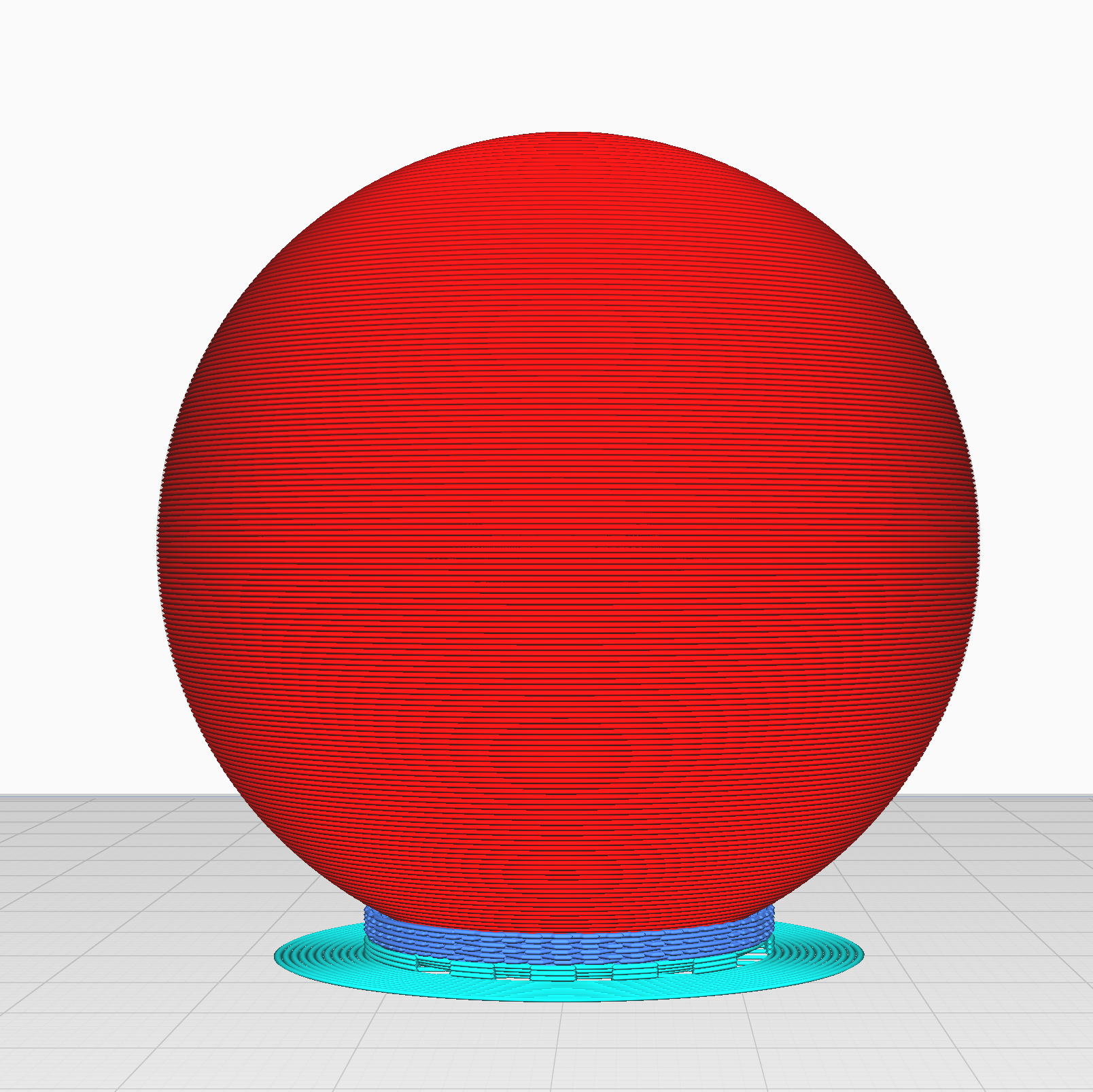
Random: Places the Z seam in a random point on every layer, this may hide the Z seam well on large very round parts
Sharpest Corner: The default option, placing the Z seam on the sharpest corner of your part

User Specified Z Seam

Random Z Seam
If any option other than Random is selected, there are a few options for how Cura selects the corner to place the Z seam, called Seam Corner Preference. They are:
None: Corners have no impact
Hide Seam: Makes the seam more likely to occur on an inside corner
Expose Seam: Makes the seam more likely to occur on an outside corner
Hide or Expose Seam: Makes the seam more likely to occur on an inside corner
Smart Hiding: Allows inside or outside corners, but picks inside corners where possible
Feedback, Ideas, or Suggestions?
If there is an issue you have been having that you would like to see us cover or if you have any other feedback, please fill out the form below!