Cart 0
Cart 0
 

Design Rules for FFF 3D Printing

This guide is intended to help you design parts for FFF 3D Printing. Applicable to any FFF 3D printer and includes best practices, design tips, and geometric limitations. Updated regularly with new information.


Table of Contents

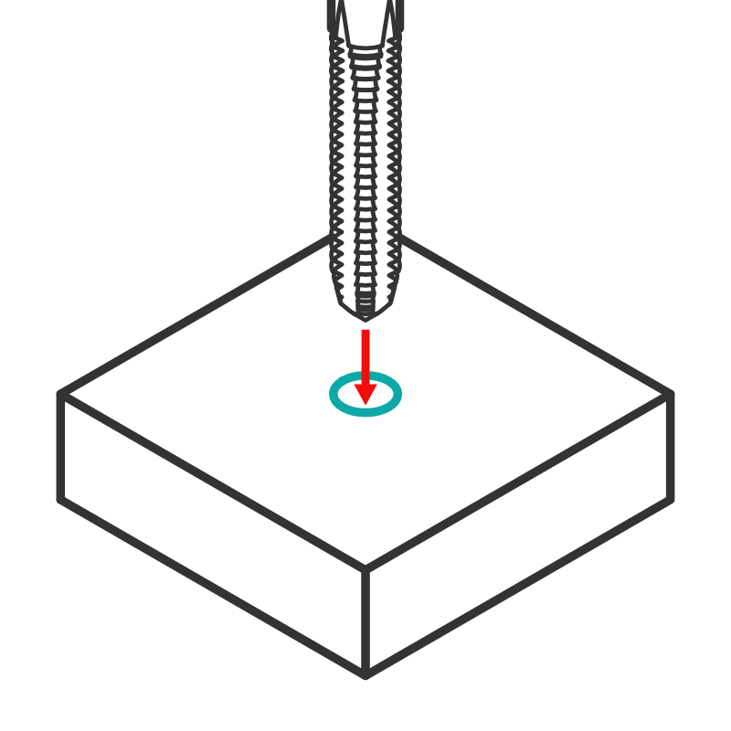
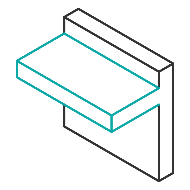
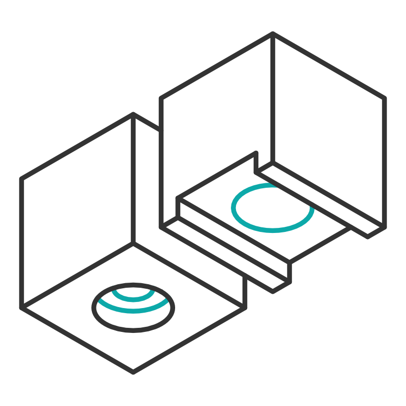
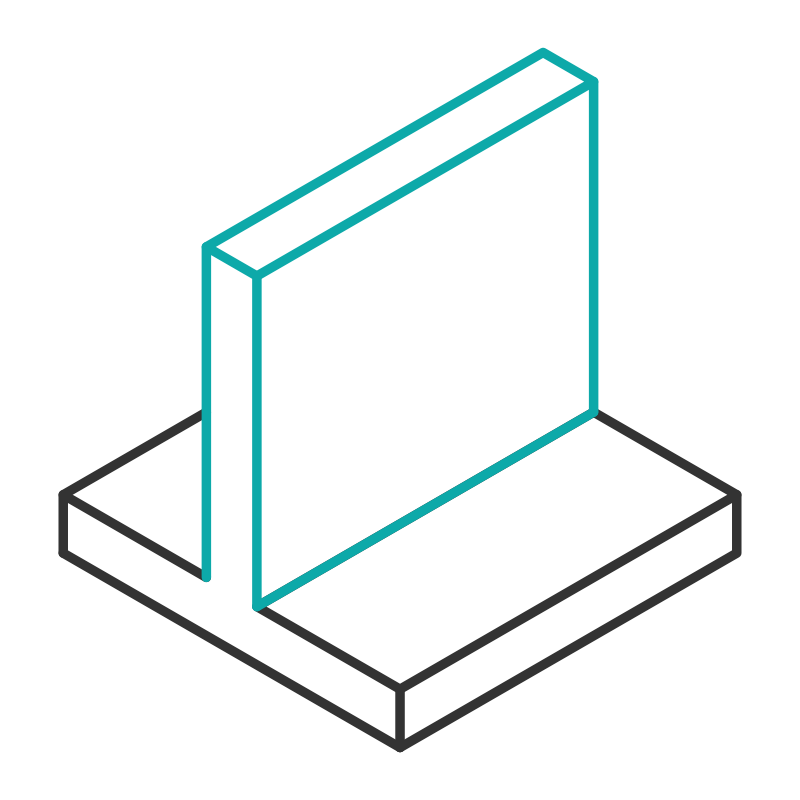
Click on the images to view full descriptions


Request a new issue to be covered or submit feedback here.


Horizontal Holes How To (800).png

Base Chamfers

Recommended Value: ~0.3 mm (initial layer height + layer height)

To improve the accuracy of the base edges of your part, it is a good idea to add a small chamfer of ~0.3 mm to all the edges that will be in contact with the print surface. This will reduce the chance of a slightly over “squished” first layer creating a lip around the base of the part. This is only relevant if you will be printing your part without a brim. If you are printing with a brim you will need to use a deburring tool our hobby knife to remove the brim a and clean up the base of the part anyway.


Base Corners (800).png

Base Corners

Recommended Value: R > 4mm

For larger parts, it is recommended to round corners that are in contact with the printer’s build plate (print surface). Sharp corners result in the shrinking forces that happen as the part cools (warping) concentrating at one point, whereas rounded corners act to disperse these forces. The larger the radius of the curved corner, the better your chances of reducing warping should be, at least in theory. A corner radius of 4mm or more is recommended.


Bridging (800).png

Bridging

Recommended Value: <10 mm

Horizontal bridges without support should not be longer than 10 mm to avoid print defects and failures. Either build vertical structures into your model to support the bridge or enable printed supports during slicing.You may find that you can bridge much larger gaps depending on the material and layer height, but keeping bridges <10 mm is a good starting point.


Clearance (800).png

Clearance

Recommended Value: ~0.3 mm for loose fit ~0.15 mm for tight fit

When 3D printed parts will fit together, a clearance of ~0.3 mm for loose fit and  ~0.15 mm for tight fit mm is recommended to ensure a good fit. The required clearance may vary slightly depending on material and geometry.


Emboss Horizontal (800).png

Emboss & Engrave Horizontal

Recommended Value Emboss: >0.9 mm wide (2 times extrusion line width)  <0.9 mm out (2 times extrusion line width)

Recommended Value Engrave: >0.5 mm wide x <0.9 mm deep (2 times extrusion line width)

To ensure embossed or engraved details on a vertical surface are resolved and visible, the line width should be at least twice your nozzle diameter in depth. They can be a little bit larger but will start to sag if they are too big.


Vertical Emboss (800).png

Emboss & Engrave Vertical

Recommended Value Emboss: >0.9 mm wide (2 times extrusion line width) x <2 mm high 

Recommended Value Engrave: >0.5 mm wide x <2 mm deep

To ensure embossed or engraved details on a horizontal surface are resolved the line width should be at least 0.5 mm wide for engraving and 0.9 mm wide for embossing. There is no limit on the height of the details, but modeling them 2 mm high will make the features clearly visible.


Feature Size (800).png

Feature Size

Recommended Value: >1.8 mm or 4 times extrusion line width

The minimum feature size for printed structures is 4 times your extrusion line width. A good rule of thumb for general modeling is making features no smaller than 1.8 mm.


Feature Size (800).png

Fillets

Recommended Value: > ø1 mm, do not use downward facing fillets

Fillets are a great way to remove sharp corners or relieve stress concentrations at sharp corners. However, it is not recommended to model downward facing fillets on 3D printed parts. Chamfers are a good alternative for downward facing edges that you may wish to soften. Downward facing fillets will not cause your print to fail, but that may come out with poor aesthetic/surface quality.


Holes (800).png

Hole Size

Recommended Value: > ø2 mm

It is not recommended to model holes with a diameter of less than 2 mm to ensure they are resolved. If an accurately sized hole of any size is necessary, undersize the hole and drill it out to the proper tolerance.


Horizontal Holes How To (800).png

Holes Horizontal 

Recommended Value: a ≈ 0.3 mm

In order to print horizontal holes with a better tolerance, it is recommended to model the additional features in the image where the offset distance a, is the layer height of your print. If you are using a small layer height like 100μm you should do 2*a. This will accommodate for any drooping that will occur in the steep overhang sections of printed horizontal holes and the “flattening” of the bottom of holes due to the stacked layer process.


Overhangs (800).png

Overhangs

Recommended Value: < 50°

To prevent layers from drooping or curling on printed overhangs, it is recommended to avoid printing unsupported overhangs at angles less than 50° (measured from the vertical axis down). Overhang quality can also be material dependent, so some materials may require support at lower angles than others.


Horizontal Holes How To (800).png

Pins

Recommended Value:  > ø1.8 mm (4 times extrusion line width)


In order to accurately resolve pins, their diameter should be at least four times the extrusion line width to ensure at least two full perimeters are printed, a good rule of thumb is ø1.8 mm. If functional pins are required in your model, it may be better to use store bought pins and model holes into both sides of the joint.


Horizontal Holes How To (800).png

Threads Modeled

Recommended Value: > M5 or UNC #10

3D printing modeled threads can work well for larger thread sizes. It is not recommended to model threads smaller than M5 or UNC #10 so that they will function effectively. If you need threads smaller than M5 or #10, they should be added with post-processing techniques such as a thread tap, or heat set threaded inserts. DO NOT use modeled/printed threads for horizontal holes.


Threads Post-Process (800).png

Threads Post-Process

Recommended Value: Tap: 90%, Self-Tap: 96%, Insert: 98%

Threads can be added in post-processing a few different ways. You can thread tap the hole, in which case model the hole at 90% of the thread diameter. You can self-tap the screw into an unthreaded hole, in which case model the hole at 96% of the thread diameter. You can also use heat-set inserts, in which case model the hole at 98% of the inserts outer diameter.


Horizontal Holes How To (800).png

Unsupported Edges

Recommended Value: < 0.9 mm (2 times extrusion line width)

It is generally recommended to avoid printing unsupported, horizontal structures that are more than two extrusion line widths wide, a good rule of thumb is 0.9 mm. It is unlikely that larger unsupported edges will cause print failures, but they will cause serious cosmetic issues. If the structures are necessary for your model, altering print orientation and/ or enabling supports will make them printable.


Unsupported Holes.jpg

Unsupported Holes

Recommended Value: Extrude 1 = layer height, Extrude 2 = layer height x 2

Without special design considerations, holes through unsupported bridges will not print successfully. This technique can be used to print such holes without adding supports to your model.

  1. When designing your part, extrude two rectangles tangent to your hole

  2. The first extrude should be as thick as the layer height you intend to print with

  3. The second extrude should be twice the layer height you intend to print with

This technique can be a little tricky to visualize until you have tried it a few times.


Wall Thickness(800).png

Wall Thickness

Recommended Value: > 0.9 mm (2 times extrusion line width)

It is strongly recommended to model walls at least two extrusions wide, generally this will be 0.9 mm. Thinner walls can have issues printing successfully and will not be very strong. Perimeters are the greatest source of strength in a 3D printed part, so if strength is important it is recommended to make walls more than two perimeters thick. Increasing perimeters will need adjustments in both modeling and slicing.


Modeling Software


Sketch Based Modeling

Autodesk Fusion 360 is the CAD (Computer Aided Design) software we use and recommend to everyone! It is robust and great for modeling parts and components. Best of all, it is free for educators and enthusiasts. Click the button below to download Fusion 360 from Autodesk's website.

Sculpting & Resolving Mesh Errors

Autodesk Meshmixer is a great free software for sculpting, working with triangle meshes, and resolving mesh errors. Meshmixer is also great for cleaning up 3D scans. Click the button below to download Meshmixer from Autodesk's website.

Mesh Based Modeling

Blender is one of the most popular mesh based modeling suites. It is useful for creating models for 3D printing as well as animation and simulations. Blender is also free and open source, it is available for download on their website.


Feedback, Ideas, or Suggestions?

If there is an issue you have been having that you would like to see us cover or if you have any other feedback, please fill out the form below!